 Tools
Tools
 Computed Tomography Instrumentation and Physics
Definition/Introduction
Computed tomography (CT) instrumentation and physics encompasses the equipment, devices, and tangible components integral to CT imaging technology. CT is a medical imaging modality that employs x-rays and computer processing to generate detailed internal body images. "Instrumentation" refers to specialized machinery and apparatus used in CT scan acquisition. Included are the x-ray tube, detectors, the circular gantry housing both the x-ray tube and detectors during rotation around the patient, the patient table, and electronic components responsible for controlling and coordinating image acquisition. The term also encompasses CT imaging properties, including fundamental principles of x-ray physics, radiation exposure considerations, and image acquisition mechanics.
Basic Principles of Computed Tomography
CT uses x-ray beams and a computer system to generate cross-sectional images of the body. CT slices demonstrate specific anatomic levels, with slice thickness selected to minimize scatter radiation and superimposition through the use of collimators.
CT data are divided into pixels arranged in a matrix, with each pixel representing distinct image information. Structures within CT images appear in varying shades of gray based on x-ray beam attenuation principles. The linear attenuation coefficient quantifies photon interaction with matter and varies according to density, atomic number, and photon energy. Increased density and higher atomic number result in greater attenuation, thereby influencing image contrast.[1]
CT images reflect these attenuation coefficients, with denser materials appearing white and less dense materials appearing black. Contrast agents, such as iodine, temporarily alter tissue density differences to enhance visualization. Hounsfield units quantify attenuation and assist in tissue characterization. However, Hounsfield unit values may demonstrate minor inaccuracies due to multiple influencing factors.
Polychromatic x-ray beams in CT may produce artifacts, such as beam hardening, which occurs when low-energy photons are preferentially absorbed. Beam filtration using materials, such as aluminum, reduces artifact formation and improves image quality while also lowering patient radiation dose.[2]
CT examinations require the selection of slice thickness based on the anatomy and suspected pathology. Thinner slices improve detection of fine detail and reduce volume averaging effects, in which normal and abnormal tissues are combined within a single voxel.
X-ray photons are generated within the gantry-mounted x-ray tube, with tube voltage and tube current regulating beam intensity.[3] Detectors convert x-ray photons into electrical signals, which are processed by the data acquisition system (DAS) and reconstructed into images by the central processing unit. CT images, commonly expressed in Hounsfield units, rely on pixel values to represent anatomic structures.
Although design variations exist, CT scanners follow standard phases consisting of data acquisition, image reconstruction, and image display. Data collection occurs during the 1st phase, followed by processing in the 2nd phase, during which pixel values are assigned. In the final phase, reconstructed data are displayed as shades of gray for interpretation.
Data Acquisition and Image Reconstruction
CT utilizes detectors that may consist of single elements or form part of a larger detector array, along with reference detectors used for calibration and artifact reduction. The size of the fan beam and the number of detector elements acquiring data depend on the selected scan field of view.[4]
Ideal detectors demonstrate high efficiency in capturing transmitted photons, minimal afterglow (persistent scintillation), effective scatter suppression, and stability that minimizes the need for frequent calibration interruptions.[5][6] Overall detector efficiency is determined by multiple factors, including the stopping power of the detector material, scintillator efficiency in solid-state detectors, charge collection efficiency in xenon detectors, geometric efficiency (comparison of detector collimator plate coverage to detector surface area), and scatter rejection.[7]
Additional parameters related to detector performance include capture efficiency (ability to acquire incident photons), absorption efficiency (proportion of photons absorbed), response time (time required for signal return to baseline after x-ray stimulation), and dynamic range (ratio of maximum to minimum measurable signal).
Modern CT scanners primarily employ solid-state crystal detectors, while older models may utilize xenon gas detectors, which are increasingly less common due to limitations in multidetector-row CT systems. Third-generation CT scanners feature a detector array and an x-ray tube that generates a fan-shaped beam, eliminating the need for beam and detector translation.[8] This design reduces scan times and motion artifacts and improves image quality, although ring artifacts may occur.
Fourth-generation scanners incorporate a fixed detector array within the gantry, while the x-ray tube rotates around the patient. Despite the increased number of detectors, this design is associated with persistent challenges related to motion artifacts. Overscanning techniques are used to mitigate these effects. However, patient radiation exposure increases as a result.[9]
Electron beam CT (EBCT) utilizes a fixed electron gun and anode target. Although high temporal resolution is achieved, the clinical utility of EBCT remains limited due to spatial resolution constraints, cost considerations, and difficulty obtaining insurance reimbursement.[10] Wider adoption of multidetector-row technology has further reduced the clinical relevance of EBCT.
Photon-counting CT (PCCT) is a major advancement in current clinical practice. Conventional detectors convert x-rays into visible light prior to signal generation, resulting in a loss of spectral information. In contrast, PCCT uses semiconductor materials, such as cadmium telluride or silicon, to directly convert individual x-ray photons into electrical signals while preserving photon energy information. Key advantages of PCCT include superior spatial resolution, improved contrast-to-noise ratio, reduced radiation dose (up to 45% lower in some studies), and intrinsic multienergy (spectral) imaging capability.[11]
The gantry DAS converts analog signals from detectors into digital signals. Continuous x-ray exposure generates signals processed by the DAS. Attenuation of each x-ray beam is correlated with spatial position, producing projection profiles for each view. These profiles are mapped onto a reconstruction matrix, which may result in streak artifacts.
Artifact reduction is achieved through filtered mathematical processing of the acquired data. Iterative reconstruction, a widely used method, refines images by comparing computed projections with the original measured data. This approach reduces image noise and radiation dose by up to 50%.[12][13] Although iterative reconstruction has been the dominant reconstruction method for many years, deep learning reconstruction (DLR) is the most recent advancement and is emerging as a new standard. DLR algorithms are trained on high-quality image datasets and reduce image noise and artifacts while preserving a more natural image texture compared with iterative reconstruction, which may produce a “waxy” appearance.[14] DLR improves lesion detection, increases soft-tissue contrast-to-noise ratio, and is particularly valuable in low-dose and pediatric imaging. Iterative reconstruction and filtered back projection remain in clinical use. However, DLR is increasingly preferred in new CT scanner installations.[15]
Image Quality and Quality Assurance
Image quality is influenced by numerous factors, some within operator control and others dependent on patient characteristics, such as body size. Operator-controlled variables include tube current (measured in milliamperes, mA), scan duration, slice thickness, field of view, reconstruction method, and kilovolt peak (kVp). Selection of pitch is also available in helical scanning techniques. Collectively, these parameters are referred to as "scanning parameters."
Image quality depends primarily on spatial and contrast resolution.[16] "Spatial resolution" refers to the ability to distinguish fine, high-contrast detail, whereas "contrast resolution" refers to the capacity to differentiate structures with similar densities. Together, these parameters contribute to diagnostic accuracy in medical imaging.
Spatial resolution is commonly evaluated using the modulation transfer function, with values ranging from 0 to 1, reflecting fidelity of object detail reproduction.[17] In-plane spatial resolution is determined by matrix size and display field of view (DFOV). Matrix size defines pixel size, while DFOV determines overall image dimensions. Increased DFOV results in larger pixels and reduced spatial resolution.
Pixel size directly affects image accuracy, with smaller pixels reducing volume averaging and improving spatial resolution. Voxel size, determined by slice thickness and matrix dimensions, also plays a critical role in spatial resolution.[18] Thinner slices and uniform voxel dimensions improve image quality. Slice thickness selection determines voxel geometry, and all tissue within a voxel is averaged to generate a single CT number.
CT systems provide multiple reconstruction algorithms that can be selected or incorporated into scan protocols to enhance or suppress specific image characteristics for optimal diagnostic performance. Certain algorithms emphasize data smoothing by reducing pixel-to-pixel variation and suppressing artifacts, albeit at the expense of spatial resolution.
Conversely, alternative reconstruction filters enhance pixel intensity differences to improve spatial resolution, but may reduce low-contrast resolution.[19] These filters are particularly useful in scenarios involving marked tissue density variation, where low-contrast detectability is less critical. "Contrast resolution" refers to the ability to distinguish subtle differences in tissue density. Subject contrast is influenced by object size, with smaller structures demonstrating reduced detectability. Organ-based contrast reflects intrinsic physical properties, such as air content in the lungs.
Temporal resolution is essential for imaging moving structures and performing dynamic contrast-enhanced studies. Temporal resolution is influenced by gantry rotation speed, detector configuration, and data acquisition speed.[20]
Quality control programs aim to optimize CT image quality while minimizing patient radiation exposure.[21] These programs systematically monitor CT system performance to identify malfunctions or performance degradation. Responsibility for quality control testing is shared between CT technologists and medical physicists. Technologists typically perform routine tests, while medical physicists conduct annual or semiannual evaluations, including acquisition of dosimetric measurements.
Quality assurance programs are based on 3 core principles. These tenets include regular performance of quality control tests, consistent documentation of results using standardized formats, and assessment of whether measured parameters meet established guidelines.[22]
Summary and Additional Points to Consider
A CT scanner consists of a gantry, which forms the external framework of the system, an x-ray tube commonly containing tungsten targets, a beam-harding filter, a collimator, and a detector system. Modern systems use either conventional solid-state detectors or photon-counting detectors, as described above. The filter preferentially removes low-energy photons, thereby reducing patient dose and mitigating beam-hardening artifacts. The resulting beam remains polyenergetic but exhibits a higher mean energy. The collimator reduces scatter radiation and defines the thickness of the x-ray beam and the reconstructed section thickness.
Compared with conventional diagnostic x-ray tubes, CT x-ray tubes operate at higher amperage and similar tube voltage, with comparable focal spot sizes. Filters are typically composed of low atomic number (low-Z) materials and function primarily to reduce low-energy photon contribution rather than to produce a monochromatic beam. Collimators regulate beam geometry and slice thickness, whereas filters modify beam energy distribution. On the detector side, septa are employed to reduce scatter and improve image quality by decreasing noise.
CT scans typically use a kVp of approximately 120, although values may range from 70 to 140. Increased kVp is associated with increased radiation dose in CT imaging. Higher kVp may reduce image noise and is often necessary for reducing metal artifacts and optimizing visualization of osseous structures. Iodinated contrast, with a K-edge of approximately 33 keV, is better visualized at lower kVp settings, typically around 80.
Mathematical filters known as kernels are applied to smooth or sharpen reconstructed data. Kernels produce images with varying levels of noise and spatial resolution. Smooth kernels improve visualization of soft tissue anatomy, whereas sharp kernels provide higher spatial resolution and are primarily used for the evaluation of osseous structures.[23]
Helical (spiral) CT acquires images by continuously rotating the x-ray tube while the patient table moves at a constant speed, reducing motion artifacts.[24] Pitch is the ratio between table travel per x-ray tube rotation and the beam width. A pitch of 1 indicates no slice overlap. A pitch greater than 1 results in gaps between slices, whereas a pitch less than 1 produces overlapping slices.[25]
DLR is currently the most advanced image reconstruction method, surpassing iterative reconstruction in many clinical applications. DLR enables lower radiation dose acquisition and reduces image noise to a greater extent while preserving more natural image texture compared with older reconstruction techniques, including back projection, filtered back projection, and conventional iterative reconstruction.
Hounsfield units quantify tissue density and attenuation. Water is assigned the reference value of 0.
Window width and level are parameters used to optimize image display for improved assessment of anatomy and pathology. Window level is the midpoint of the gray scale and is typically centered on the attenuation characteristics of the target tissue. Window width is the range of attenuation values displayed.
Comparison of bone and soft tissue requires a wide window width. Evaluation of tissues with similar attenuation requires a narrow window width.
Automatic exposure control adjusts mA but does not alter kVp. Increasing mA by a factor of 4 increases the signal-to-noise ratio (SNR) by a factor of 2 while increasing the radiation dose by a factor of 4.[26]
Issues of Concern
Register For Free And Read The Full Article
 Search engine and full access to all medical articles
- 10 free questions in your specialty
- Free CME/CE Activities
- Free daily question in your email
- Save favorite articles to your dashboard
- Emails offering discounts
Learn more about a Subscription to StatPearls Point-of-Care
Issues of Concern
CT artifacts may arise from multiple sources and manifest in various forms, broadly categorized as physics-based (related to data acquisition), patient-related, or equipment-induced. Such artifacts can significantly degrade image quality, requiring accurate identification, understanding, and appropriate strategies for reduction or prevention (see Image. Peripheral Artifact on Head Computed Tomography). Identification of artifact sources conserves time and resources by enabling prompt correction or servicing interventions.
Image Noise
Image noise appears as grainy artifacts and may result from multiple factors, including quantum noise due to insufficient detected photons. Reduction of noise improves contrast resolution. Adjustment of mAs directly affects photon flux, thereby influencing SNR and contrast resolution. However, increased mAs also increases radiation dose.[27] Smaller pixel size reduces the number of photons per pixel, increasing noise and reducing contrast resolution. Slice thickness influences photon statistics and SNR, with thicker slices improving SNR but reducing spatial resolution. Larger patient size increases photon attenuation, resulting in reduced SNR and decreased contrast resolution.[28]
Beam Hardening
Beam hardening occurs due to the polychromatic nature of the x-ray beam. Lower-energy photons are preferentially absorbed as the beam passes through tissue, resulting in a higher mean beam energy. This effect produces artifacts, such as cupping artifacts and streaking between dense structures. Beam filtration, system calibration, and beam-hardening correction algorithms are used to reduce these artifacts in CT systems.[29]
Partial Volume Artifact
Partial volume artifact arises when multiple tissue types are included within a single voxel, typically occurring at interfaces involving dense structures at the edge of the field of view.[30] The resulting effect produces shading artifacts. Thinner slices are used to reduce this type of artifact.[31]
Aliasing
Aliasing occurs when insufficient projection data are acquired, resulting in inaccurate reconstruction of sharp edges and small objects. The artifact manifests as fine streaks radiating from dense structures. Reduction of aliasing may be achieved by adjusting the gantry rotation speed or helical pitch.[32]
Edge Gradient Effect
Edge gradient effect produces streaking or shading artifacts due to irregularly shaped structures with large attenuation differences relative to surrounding tissues. Obtaining thinner slices reduces the severity of this artifact. Low-attenuation oral contrast or water can reduce streak artifacts within the gastrointestinal tract.[33]
Motion
Motion produces shading, ghosting, streaking, or blurring artifacts in CT images (see Image. Motion Artifact on Head Computed Tomography). CT systems incorporate overscan and partial scan modes, software-based correction algorithms, and cardiac gating techniques to reduce motion-related artifacts. Voluntary motion is minimized by proper patient preparation and education, the use of positioning aids, and sedation when necessary. Reduction of scan duration in chest and abdominal imaging further diminishes motion artifacts.
Metallic Artifacts
Metallic artifacts arise from metal objects within the scan field of view (see Image. Metallic Artifacts on Pelvic Computed Tomography). Metal attenuation frequently exceeds the dynamic range of CT Hounsfield units, resulting in severe streak artifacts. Newer CT systems provide expanded Hounsfield unit ranges. However, minimizing metallic objects within the scan field of view remains essential. Removal of external metal objects and adjustment of scanning parameters, when feasible, may reduce artifact severity.[34]
Deep learning–based metal artifact reduction (MAR) is a highly effective contemporary approach. Multiple deep learning–based MAR techniques have been developed, including KMAR-Net for knee arthroplasty, which demonstrates superior performance compared with conventional MAR methods.[35] These artificial intelligence–based methods are increasingly available on modern CT systems and substantially reduce streak artifacts while improving preservation of diagnostic information.
Ring Artifacts
Ring artifacts are typically observed in 3rd-generation CT scanners and appear as concentric rings centered on the rotational axis. Ring artifacts result from malfunctioning or misaligned detector elements and may require recalibration or intervention by a service engineer. Recent advancements demonstrate that artificial intelligence can effectively reduce ring artifacts in medical imaging.[36][37]
Tube Arcing
Tube arcing is an equipment-induced artifact caused by short circuits within the x-ray tube, often related to differences in electrical potential. Contributing factors include tube aging, changes in vacuum conditions, and the presence of residual gas molecules within the tube.[38] Tube arcing may produce artifacts, ranging from subtle streaking to severe image distortion. Evaluation by a service engineer is required when tube arcing is suspected to enable corrective action.
Helical Computed Tomography and Reconstruction-Related Artifacts
Helical CT introduces additional artifacts related to interpolation during image reconstruction. Reduction of these artifacts is achieved through the use of lower pitch values when clinically feasible. In multidetector CT systems, the cone beam effect may introduce artifacts, particularly in outer detector rows, with severity increasing as cone beam width increases. Certain protocols restrict data acquisition to central detector rows to improve image quality.
Additional artifacts may occur during multiplanar reformations and 3-dimensional reconstructions derived from original acquisition data. Careful protocol selection is required to minimize artifact propagation in reconstructed and reoriented image datasets.
Clinical Significance
Understanding CT physics is essential for recognizing artifacts that affect image quality and diagnostic interpretation. CT physics underpins the principles governing image acquisition and reconstruction, directly influencing image quality and diagnostic utility.
Image quality directly affects diagnostic adequacy. For example, an image of an infant acquired using a low-dose technique may appear noisy. However, such an image may remain clinically sufficient when used for follow-up of a significant abnormality, such as an abscess.
Radiologists and technologists must understand physics-related factors that introduce imaging artifacts, including beam hardening, partial volume effects, and metallic artifacts. This knowledge enables prompt identification of artifacts and application of appropriate corrective measures.
An in-depth understanding of CT physics improves diagnostic accuracy and supports optimal patient care. Reduction of image artifacts allows more precise diagnosis, decreases the need for repeat scans, reduces radiation exposure, and facilitates earlier initiation of necessary medical interventions. Understanding CT physics improves identification and correction of imaging artifacts, supporting diagnostic accuracy and patient care.
Nursing, Allied Health, and Interprofessional Team Interventions
Healthcare professionals, including radiologic technologists and radiologists, must possess technical proficiency in operating CT systems and accurately interpreting resultant images. Clinical skills are also essential for correlating CT findings with patient medical history and physical examination findings to support accurate diagnosis.
Systematic planning is essential in the utilization of CT imaging. Strategic approaches include the appropriate selection of imaging protocols and sequencing to address specific clinical questions efficiently. Physicians and radiologists must also implement strategies to minimize radiation exposure, particularly in vulnerable populations, such as pregnant patients and children. Ethical considerations play a central role in the responsible use of CT imaging. Healthcare professionals must ensure informed consent is obtained from patients or guardians, with a clear understanding of associated risks and benefits. Ethical practice also requires adherence to the principle of using the lowest reasonable radiation dose while maintaining diagnostic image quality. Interprofessional collaboration is required to ensure appropriate implementation of these practices.
Physicians are responsible for ordering appropriate CT scans, interpreting results, and communicating findings to patients and the healthcare team. Nurses are responsible for patient preparation, monitoring vital signs, and providing emotional support during CT procedures. Pharmacists, while not directly involved in image acquisition, ensure appropriate medication management before and after imaging, particularly in cases involving contrast administration.
Effective interprofessional communication is essential for high-quality care delivery. Clear and timely exchange of critical information, including imaging findings, patient status, and medication requirements, is required among physicians, radiologists, nurses, pharmacists, and other healthcare professionals. Radiologists must communicate findings in a manner that is understandable to nonspecialist team members. Radiologic technologists play a frontline role in ensuring equitable patient care through culturally sensitive communication and the use of accessible resources that support patient understanding of CT procedures, regardless of language or background.[39]
Care coordination is integral to ensuring a seamless patient journey in CT imaging, encompassing management of patient scheduling, allocation of radiologic technologists, and organization of postscan care. Physicians are also responsible for coordinating follow-up evaluations based on CT results and involving appropriate specialists when indicated.
Patient-centered care requires active patient participation in decision-making. Healthcare professionals should address patient concerns, provide clear and understandable information, and involve patients in decisions regarding CT imaging and subsequent management. Patient safety requires systematic verification processes, including confirmation of patient identity, assessment of allergies to contrast media, and monitoring for adverse reactions during and after contrast administration.
Enhancement of team performance requires regular training and interprofessional team meetings. Such activities allow healthcare professionals to remain updated on best practices, safety protocols, and advancements in CT technology, thereby improving coordination and quality of care.
Media
(Click Image to Enlarge)
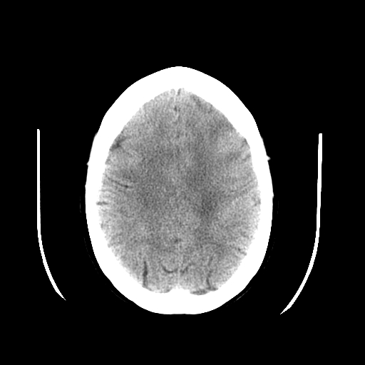
Peripheral Artifact on Head Computed Tomography. This axial image demonstrates a distinct, halo-like artifact composed of symmetric curved lines external to the skull.
Contributed by S Dulebohn, MD
(Click Image to Enlarge)
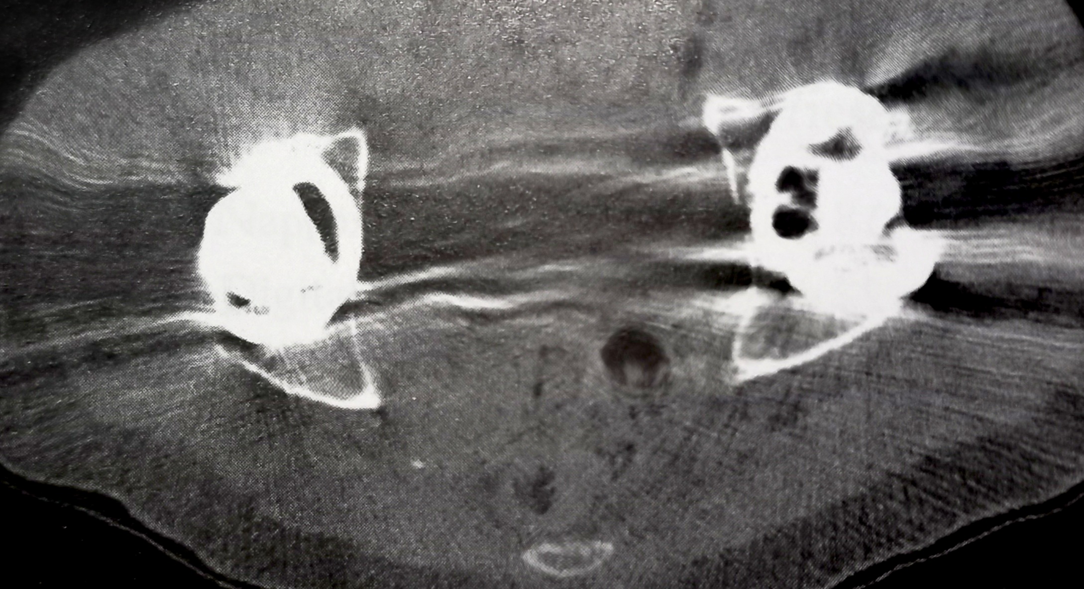
Metallic Artifacts on Pelvic Computed Tomography. This axial scan of the pelvis demonstrates severe streak artifacts radiating from bilateral metallic hip prostheses. The metal attenuation exceeds the dynamic range of Hounsfield units, creating severe image degradation across the surrounding soft tissues.
Contributed by Orlando De Jesus
(Click Image to Enlarge)
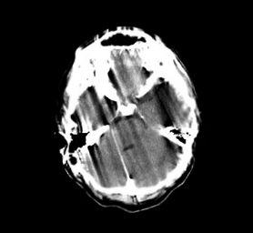
Motion Artifact on Head Computed Tomography. This axial scan exhibits severe, widespread streaking and shading artifacts cutting vertically through the brain parenchyma.
Contributed by Khadija Ghumman
References
Goldman LW. Principles of CT and CT technology. Journal of nuclear medicine technology. 2007 Sep:35(3):115-28; quiz 129-30 [PubMed PMID: 17823453]
Mazonakis M, Damilakis J. Computed tomography: What and how does it measure? European journal of radiology. 2016 Aug:85(8):1499-504. doi: 10.1016/j.ejrad.2016.03.002. Epub 2016 Mar 10 [PubMed PMID: 26995675]
Seeram E. Computed Tomography: A Technical Review. Radiologic technology. 2018 Jan:89(3):279CT-302CT [PubMed PMID: 29298954]
Seeram E. Computed Tomography: Physical Principles and Recent Technical Advances. Journal of medical imaging and radiation sciences. 2010 Jun:41(2):87-109. doi: 10.1016/j.jmir.2010.04.001. Epub 2010 Jun 8 [PubMed PMID: 31051822]
Level 3 (low-level) evidenceHsieh J, Gurmen OE, King KF. Investigation of a solid-state detector for advanced computed tomography. IEEE transactions on medical imaging. 2000 Sep:19(9):930-40 [PubMed PMID: 11127606]
McCollough CH, Leng S, Yu L, Fletcher JG. Dual- and Multi-Energy CT: Principles, Technical Approaches, and Clinical Applications. Radiology. 2015 Sep:276(3):637-53. doi: 10.1148/radiol.2015142631. Epub [PubMed PMID: 26302388]
Fuchs T, Kachelriess M, Kalender WA. Direct comparison of a xenon and a solid-state CT detector system: measurements under working conditions. IEEE transactions on medical imaging. 2000 Sep:19(9):941-8 [PubMed PMID: 11127607]
Christe A, Heverhagen J, Ozdoba C, Weisstanner C, Ulzheimer S, Ebner L. CT dose and image quality in the last three scanner generations. World journal of radiology. 2013 Nov 28:5(11):421-9. doi: 10.4329/wjr.v5.i11.421. Epub [PubMed PMID: 24349646]
Level 2 (mid-level) evidenceDubois PJ, Kennerdell JS, Rosenbaum AE. Advantages of a fourth generation CT scanner in the management of patients with orbital mass lesions. Computerized tomography. 1979:3(4):279-90 [PubMed PMID: 519980]
Level 3 (low-level) evidenceKulkarni S, Rumberger JA, Jha S. Electron Beam CT: A Historical Review. AJR. American journal of roentgenology. 2021 May:216(5):1222-1228. doi: 10.2214/AJR.19.22681. Epub 2021 Mar 24 [PubMed PMID: 33760655]
Schwartz FR, Sodickson AD, Pickhardt PJ, Sahani DV, Lev MH, Gupta R. Photon-Counting CT: Technology, Current and Potential Future Clinical Applications, and Overview of Approved Systems and Those in Various Stages of Research and Development. Radiology. 2025 Mar:314(3):e240662. doi: 10.1148/radiol.240662. Epub [PubMed PMID: 40067107]
Level 3 (low-level) evidenceStiller W. Basics of iterative reconstruction methods in computed tomography: A vendor-independent overview. European journal of radiology. 2018 Dec:109():147-154. doi: 10.1016/j.ejrad.2018.10.025. Epub 2018 Oct 26 [PubMed PMID: 30527298]
Level 3 (low-level) evidenceSeeram E, Seeram D. Image Postprocessing in Digital Radiology-A Primer for Technologists. Journal of medical imaging and radiation sciences. 2008 Mar:39(1):23-41. doi: 10.1016/j.jmir.2008.01.004. Epub 2008 Mar 22 [PubMed PMID: 31051771]
Kobayashi N, Nakaura T, Yoshida N, Nagayama Y, Kidoh M, Uetani H, Sakabe D, Kawamata Y, Funama Y, Tsutsumi T, Hirai T. Impact of deep learning reconstruction on radiation dose reduction and cancer risk in CT examinations: a real-world clinical analysis. European radiology. 2025 Jun:35(6):3499-3507. doi: 10.1007/s00330-024-11212-6. Epub 2024 Nov 29 [PubMed PMID: 39613960]
Chandran M O, Pendem S, P S P, Chacko C, - P, Kadavigere R. Influence of deep learning image reconstruction algorithm for reducing radiation dose and image noise compared to iterative reconstruction and filtered back projection for head and chest computed tomography examinations: a systematic review. F1000Research. 2024:13():274. doi: 10.12688/f1000research.147345.1. Epub 2024 Apr 15 [PubMed PMID: 38725640]
Level 1 (high-level) evidenceTang X, Krupinski EA, Xie H, Stillman AE. On the data acquisition, image reconstruction, cone beam artifacts, and their suppression in axial MDCT and CBCT - A review. Medical physics. 2018 Jul 17:():. doi: 10.1002/mp.13095. Epub 2018 Jul 17 [PubMed PMID: 30019342]
Nickoloff EL, Riley R. A simplified approach for modulation transfer function determinations in computed tomography. Medical physics. 1985 Jul-Aug:12(4):437-42 [PubMed PMID: 4033588]
Pan X, Yu L, Kao CM. Spatial-resolution enhancement in computed tomography. IEEE transactions on medical imaging. 2005 Feb:24(2):246-53 [PubMed PMID: 15707250]
Willemink MJ, Noël PB. The evolution of image reconstruction for CT-from filtered back projection to artificial intelligence. European radiology. 2019 May:29(5):2185-2195. doi: 10.1007/s00330-018-5810-7. Epub 2018 Oct 30 [PubMed PMID: 30377791]
Mergen V, Sartoretti T, Cundari G, Serifovic M, Higashigaito K, Allmendinger T, Schmidt B, Flohr T, Manka R, Eberhard M, Alkadhi H. The Importance of Temporal Resolution for Ultra-High-Resolution Coronary Angiography: Evidence From Photon-Counting Detector CT. Investigative radiology. 2023 Nov 1:58(11):767-774. doi: 10.1097/RLI.0000000000000987. Epub 2023 May 22 [PubMed PMID: 37222522]
Appel E, Kröpil P, Bethge OT, Aissa J, Thomas C, Antoch G, Boos J. Quality assurance in CT: implementation of the updated national diagnostic reference levels using an automated CT dose monitoring system. Clinical radiology. 2018 Jul:73(7):677.e13-677.e20. doi: 10.1016/j.crad.2018.02.012. Epub 2018 Mar 20 [PubMed PMID: 29567269]
Level 2 (mid-level) evidenceGreen CA, Solomon JB, Ruchala KJ, Samei E. Design and implementation of a practical quality control program for dual-energy CT. Journal of applied clinical medical physics. 2021 Oct:22(10):249-260. doi: 10.1002/acm2.13396. Epub 2021 Sep 2 [PubMed PMID: 34472700]
Level 2 (mid-level) evidenceWillaume T, Delmas L, Tochon L, Bierry G. A comparison of smooth and sharp kernel CT reconstructions in the detection of unilateral sacral fractures. Skeletal radiology. 2023 Aug:52(8):1519-1524. doi: 10.1007/s00256-023-04313-8. Epub 2023 Mar 4 [PubMed PMID: 36869891]
Heiken JP, Brink JA, Vannier MW. Spiral (helical) CT. Radiology. 1993 Dec:189(3):647-56 [PubMed PMID: 8234684]
Wang G, Vannier MW. The effect of pitch in multislice spiral/helical CT. Medical physics. 1999 Dec:26(12):2648-53 [PubMed PMID: 10619250]
Söderberg M, Gunnarsson M. Automatic exposure control in computed tomography--an evaluation of systems from different manufacturers. Acta radiologica (Stockholm, Sweden : 1987). 2010 Jul:51(6):625-34. doi: 10.3109/02841851003698206. Epub [PubMed PMID: 20429764]
Barrett JF, Keat N. Artifacts in CT: recognition and avoidance. Radiographics : a review publication of the Radiological Society of North America, Inc. 2004 Nov-Dec:24(6):1679-91 [PubMed PMID: 15537976]
Tao S, Rajendran K, Zhou W, Fletcher JG, McCollough CH, Leng S. Noise reduction in CT image using prior knowledge aware iterative denoising. Physics in medicine and biology. 2020 Nov 19:65(22):. doi: 10.1088/1361-6560/abc231. Epub 2020 Nov 19 [PubMed PMID: 33065559]
Wang H, Xu Y, Shi H. A new approach for reducing beam hardening artifacts in polychromatic X-ray computed tomography using more accurate prior image. Journal of X-ray science and technology. 2018:26(4):593-602. doi: 10.3233/XST-17325. Epub [PubMed PMID: 29562575]
Kalisz K, Buethe J, Saboo SS, Abbara S, Halliburton S, Rajiah P. Artifacts at Cardiac CT: Physics and Solutions. Radiographics : a review publication of the Radiological Society of North America, Inc. 2016 Nov-Dec:36(7):2064-2083 [PubMed PMID: 27768543]
Zou Y, Sidky EY, Pan X. Partial volume and aliasing artefacts in helical cone-beam CT. Physics in medicine and biology. 2004 Jun 7:49(11):2365-75 [PubMed PMID: 15248583]
Stockham CD. A simulation study of aliasing in computed tomography. Radiology. 1979 Sep:132(3):721-6 [PubMed PMID: 472254]
Joseph PM, Spital RD. The exponential edge-gradient effect in x-ray computed tomography. Physics in medicine and biology. 1981 May:26(3):473-87 [PubMed PMID: 7243880]
Wellenberg RHH, Hakvoort ET, Slump CH, Boomsma MF, Maas M, Streekstra GJ. Metal artifact reduction techniques in musculoskeletal CT-imaging. European journal of radiology. 2018 Oct:107():60-69. doi: 10.1016/j.ejrad.2018.08.010. Epub 2018 Aug 12 [PubMed PMID: 30292274]
Lee J, Chae HD, Cho H, Kim JM, Hong SH, Choi JY, Yoo HJ, Ye SJ. Deep learning-based metal artifact reduction in CT for total knee arthroplasty. Scientific reports. 2025 Nov 12:15(1):39587. doi: 10.1038/s41598-025-21012-7. Epub 2025 Nov 12 [PubMed PMID: 41224803]
Chao Z, Kim HJ. Removal of computed tomography ring artifacts via radial basis function artificial neural networks. Physics in medicine and biology. 2019 Dec 5:64(23):235015. doi: 10.1088/1361-6560/ab5035. Epub 2019 Dec 5 [PubMed PMID: 31639777]
Al-Naser YA. The impact of artificial intelligence on radiography as a profession: A narrative review. Journal of medical imaging and radiation sciences. 2023 Mar:54(1):162-166. doi: 10.1016/j.jmir.2022.10.196. Epub 2022 Nov 12 [PubMed PMID: 36376210]
Level 3 (low-level) evidenceMithun S, Jha AK, Panchal K, Purandare NC, Shah S, Agrawal A, Rangarajan V. A rare cause of tube arcing artifact seen in computed tomography image of a positron emission tomography/computed tomography scanner. The Indian journal of radiology & imaging. 2016 Jan-Mar:26(1):153-5. doi: 10.4103/0971-3026.178368. Epub [PubMed PMID: 27081241]
Al-Naser Y, Sharma S, Patlas MN, Yong-Hing C. The Medical Radiation Technologist's Role in Increasing Equity, Diversity, and Inclusion in the Radiology Department. Canadian Association of Radiologists journal = Journal l'Association canadienne des radiologistes. 2024 Nov:75(4):693-694. doi: 10.1177/08465371241254967. Epub 2024 May 16 [PubMed PMID: 38752414]